
Hey, Nasser here 👋
There’s a common misconception in CFD simulation circles.
It’s those “we’ve always done it this way” thinking that get’s us trapped.
And I fell for it too.
I spent over a decade (13 years in fact) as a professional Design Engineer using simulation tools like CFD and FEA in practice, using it in “expected” way.
In industry, mesh refinements are usually driven by an understanding of the relevant fluid dynamics of a problem and initial simulation runs.
Like some of you, this got me so far as to do “comparative” simulation studies, not using CFD tools intentionally with clarity.
But all that changed when I became a software developer working on physics engines and numerical solvers later in my career…
I got to look at and work on the actual code – revealing far more than a CFD training manual did!
Since over-refined meshes or large cell counts directly impact the computational solve time and the ability to practically run multiple simulations on geometry variations, I really want to know:
What’s the most effective quality metric as seen by the solver?
…and it’s not what you think.
How OpenFOAM sees that mesh of yours
OpenFOAM doesn’t see the mesh, the cells, the layers or geometry…
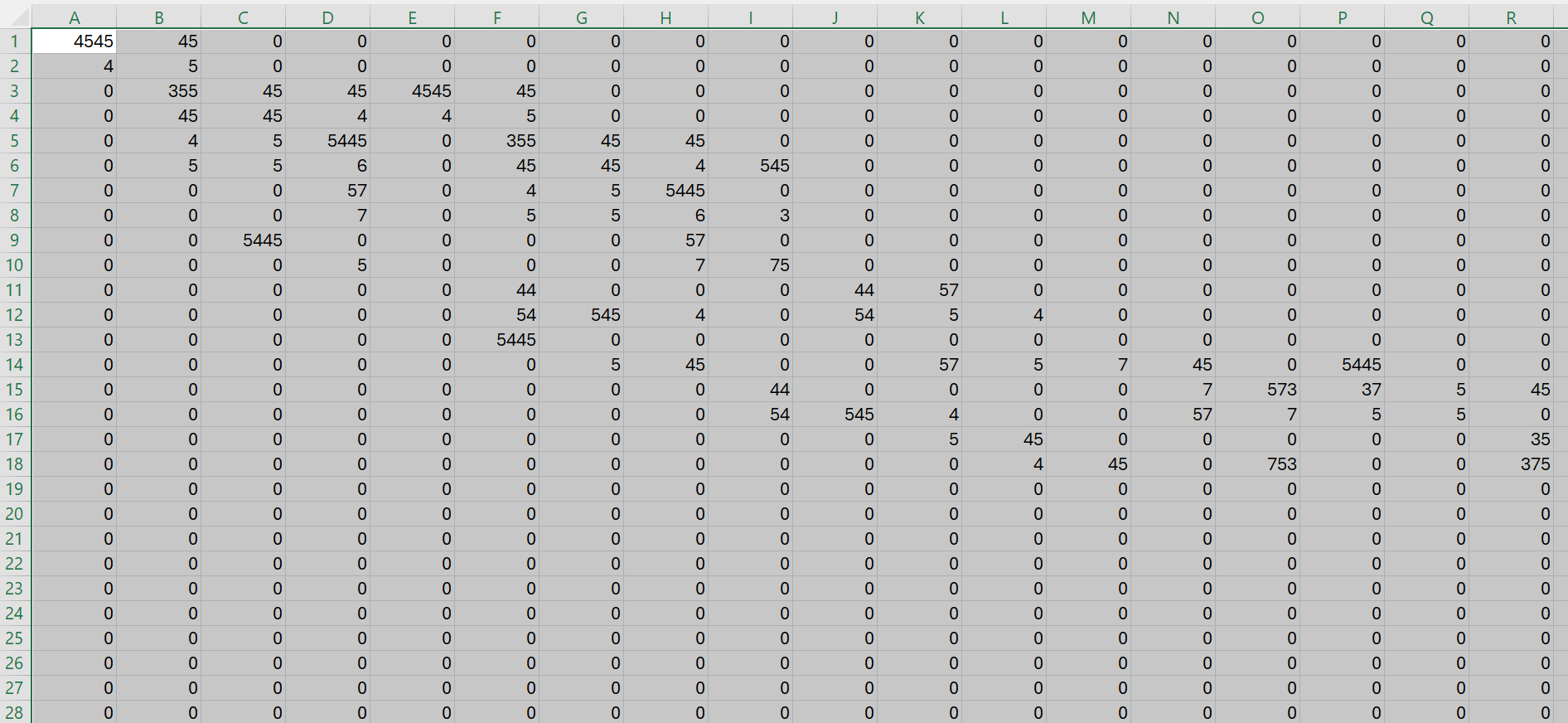
It actually builds a large table of cells and rows, aka “large, sparse, coupled matrix” (This is the “fvMatrix” class in OpenFOAM code for the curious).
It takes each cell you’ve generated and gives it a row, with it’s neighbouring cells. These will be checked during the solver at each iteration.
Most of this table is set to ‘0’ (zero) where no neighbour relationship exists.
It’s kind of like an Excel spreadsheet with each cell as a row and the neighbouring cells “coupled” to check for influence for the various field values (U, p etc).
This is a table built directly from your mesh, but why should you care as an end-user?
How to setup a mesh the CFD Solver prefers
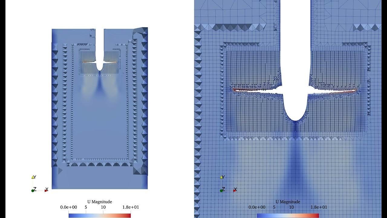
A perfectly orthogonal mesh that’s aligned to the flow gradient is an ideal case in which OpenFOAM can iterate and solve the fluid equations with minimal correction. However, if this is not the case, it will have to do more work, potentially correcting for millions of cells per iteration.
The key parameters and knobs to tweak are:
-
Non-orthogonality
-
Face skewness
-
Alignment with gradients
-
Smooth size transitions
Always use utilities like checkMesh!
Maybe I’ll show / walk through a practical example in a future post.
How did you find this post?
Consider upgrading your subscription to paid (annual includes a few months free) if you want to support me directly (access my additional resources and exclusive member-only chat to discuss your specific simulation case).
Leave a comment or e-mail me at hi@nasserm.com!
See you soon.