
This post is part of a series, demonstrating a practical investigation using OpenFOAM for CFD simulation and analyses.
If you missed the previous posts, take a look here:
We have a mock Air Inlet Manifold here with a single inlet and four outlets, symmetric in design.
I want to extract the pressure drop and mass flow rate across the runners.
Why? Well, these give us an indication on how well the flow is being distributed to the four outlets that would actually be feeding a 4-cylinder engine.
If we excuse the blocky design for now (I’ll do a more realistic one in the future), the goal is to get you to understand how to do things with OpenFOAM and, more importantly, why it’s done this way.
Taking a section through the 3D field.
You can look at these slices as 2D cuts within the larger 3D field.
This is also known as “spatial” data – specifically velocity in x, y and z.
The values at each cell face are calculated by the solver and is displayed at a given time step (smoothed if you selected the ‘cell-to-point filtered data’ option in ParaView).
And the time it take to cut this and manipulate it is incredibly fast thanks to the great tools, algorithms and modern computers.
Sometimes we forget how good we have it..!
I need to zone in on a single runner.
What we currently have is the field distribution.
And we can see:
-
The pressure gradients
-
The velocity magnitude and direction
-
The non-uniformity in the flow
But we need to drill down into one outlet and extract the pressure values from that to get what we need in order calculate the mass flow rate.
To do this OpenFOAM provides Function Objects (Utilities that make your life easier!).
And there’s literally 100’s of them!
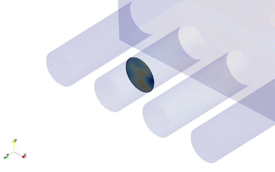
I created a bounded clipped plane using a function object (this is just a visual extraction of the mesh cells in vtp format).
To really isolate it, you need to define a ‘bounds’ value, restricting the cut plane to an X and Y extent of the runner surface…
Extracting the field values.
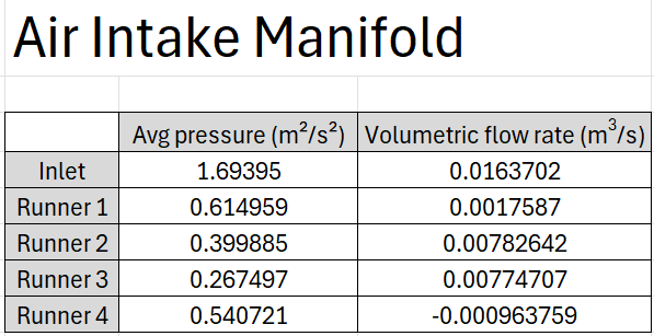
We need the average pressures and mass flow rates at each runner to ultimately calculate the percentage of flow running through each (the flow distribution).
I used the surfaceFieldValue functionObject to define a plane (see usage help in the docs for setup: https://doc.openfoam.com/2606/tools/post-processing/function-objects/field/surfaceFieldValue/).
The naming of each function object makes general sense and crawling the documentation becomes so much easier when you have this focus on what you want from it.
Remember, OpenFOAM is really a toolkit.
I like to think of it as generalised commercial software broken into pieces, so we can use only what we need at any given time.
That’s it for Part 1.
I’ll follow up on this soon and turn this raw data into useful calculated values.
If these posts save you time in trial and error, becoming a paid subscriber helps me spend more of my time running these investigations and sharing the results with you. I provide them with my insights and additional resources that help get you build your own skills faster with complete clarity.
Get access to the exact template with functionObjects I’ve setup to use on your own cases below and save time!
See you soon. 👋
Nasser
