
Most Engineers struggle to generate a good mesh, valid for the CFD simulation.
Yet the mesh is the source of truth in the eyes of the Solver.
If you have a poor mesh, you’ll likely experience:
-
The Solver refusing to start (due to geometry / topology errors)
-
The Solver running but struggling (discretisation quality issues)
-
The results diverging or revealing strange physics results (numerical instability)
I know exactly how frustrating it can be to generate a mesh only to find the Solver failing to compute past a certain percentage or waiting after a long solve time only to find odd, non-physical results.
You’ve probably heard the saying “Who has the mesh, owns the results..”
I don’t know who said it first but I believe this statement to be mostly true, considering how CFD Solvers work under-the-hood.
So, over the years as a Senior Mechanical Engineer, I’ve had to learn how to generate a good mesh – one that the Solver likes, for my industrial design projects.
Let’s go!
Starting off on the right foot…
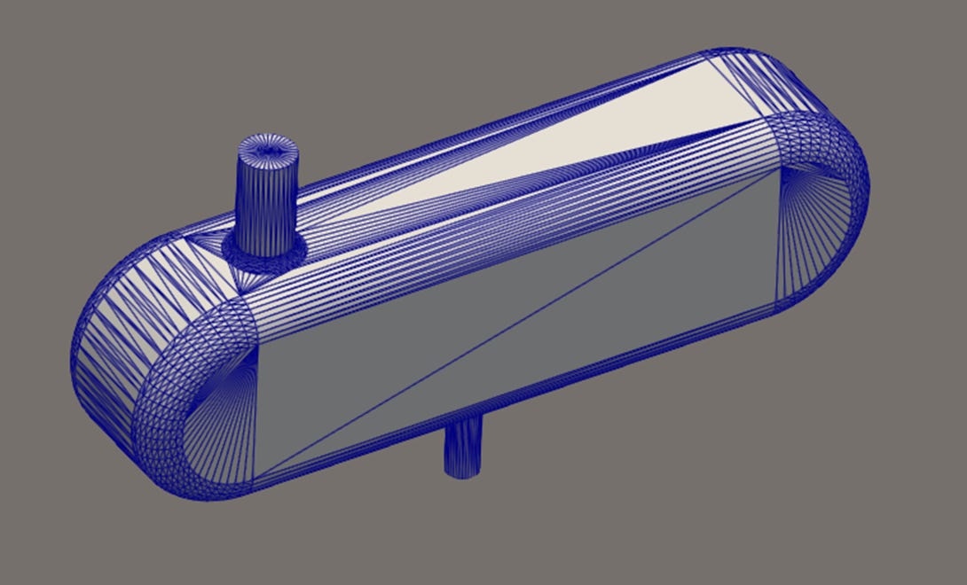
First, SHM works by needing a clean base mesh to recursively refine from.
If you missed last weeks post, you might want to check that out first which details how it generally works:
The triangulation of your model generally doesn’t make a real difference for the first (castellation) stage of the process.
But it does matter in the second and third stages it uses (snapping and layers).
I haven’t gone deep into the algorithms used by SHM (yet?), but I suspect it’s a case of using the model information regionally (edges and points) to refine based on local parameters.
So, always start with a well-defined STL model – check the export settings in your CAD program to manipulate the quality, ensuring you capture all the edges necessary (some tools let you preview before the export!).
So many parameters but only a hand-full give you the results…
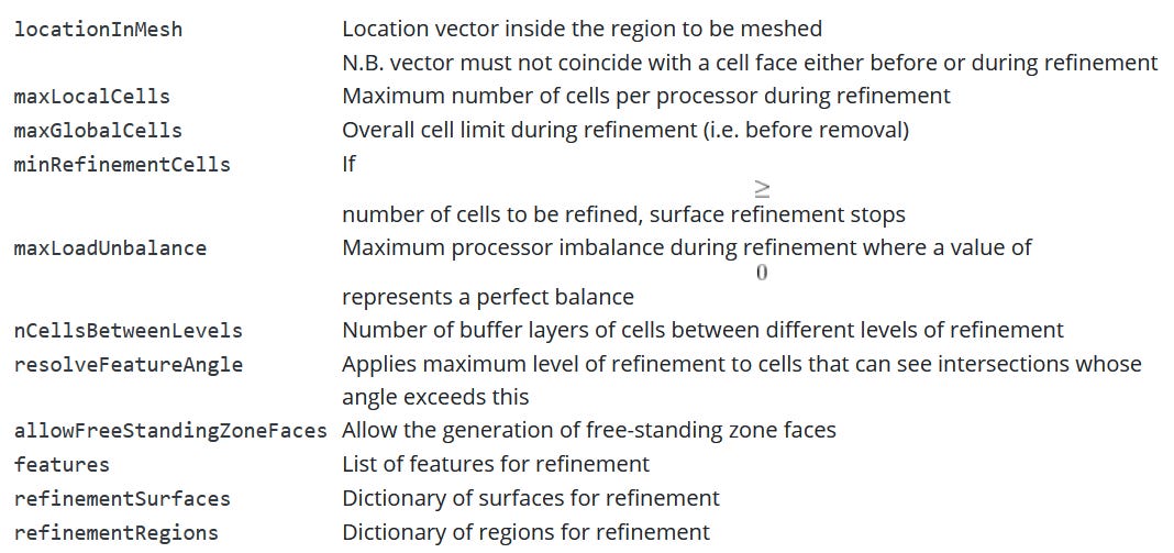
There are at least 50+ parameters to set and tweak in a typical SHM dictionary file.
And some of them have additional settings and need to be referenced back to your geometry.
Things can get tricky really fast, especially as a beginner or casual user…
The SHM knobs and settings that truly matter
From my own experience and obsession to practically test what has a significant impact and what doesn’t, I’ve come to find that only a few parameters make the difference to the actual results.
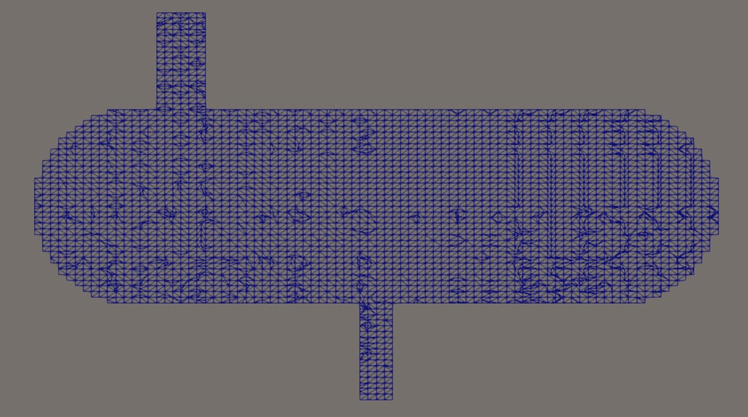
Note, this week I got through the castellation stage only (SHM’s refinement and mesh cutting stage, no snapping or layers).
Let’s take a walk…
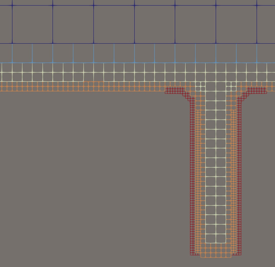
castellatedMeshControls > features
-
I set the Features.level setting to (4) and the flat edges were mostly picked up but not all and it was not al all uniform…
-
Controls feature edge refinement based on the .eMesh file
-
I found this significant when I had sharp edges in my model – it didn’t appear to do anything when when I had curved surfaces only
castellatedMeshControls > refinementSurfaces
-
Example refinementSurfaces.level (2 2):
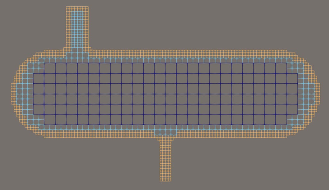
-
Example refinementSurfaces.level (2 3):
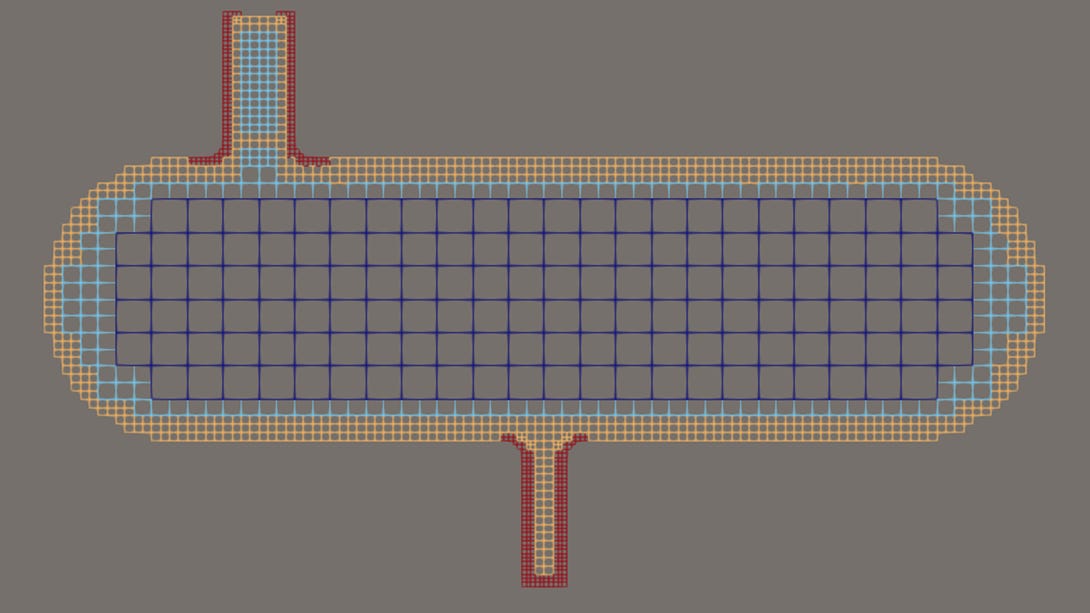
-
Example refinementSurfaces.level (3 4):
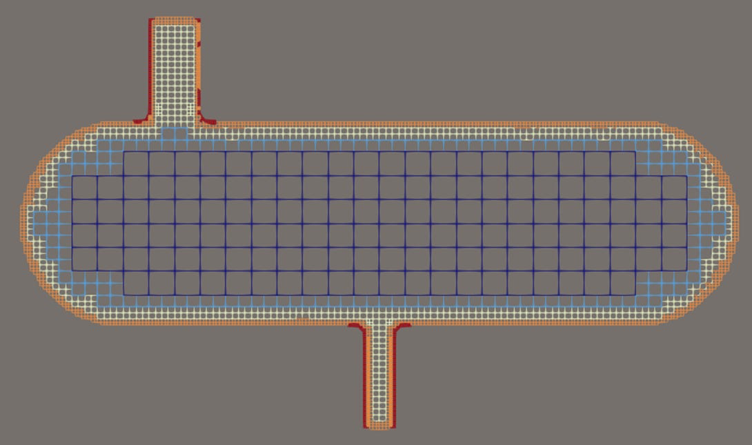
-
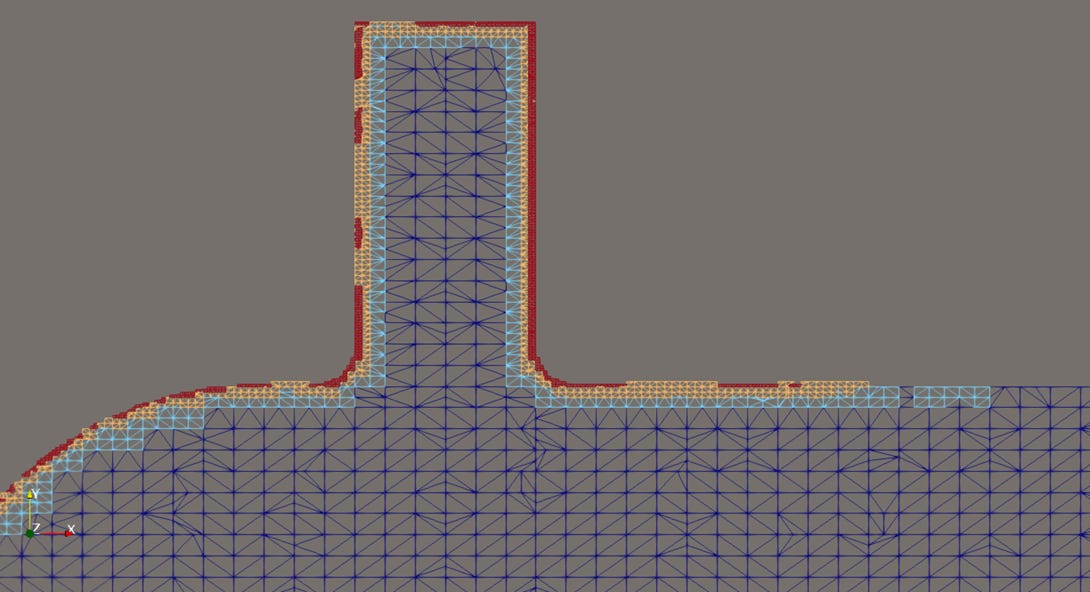
Controls the refinement behaviour near the surfaces of the model
-
Interesting results, more like I expected to see and definitely gave the control I needed using the surface as a reference for refinement
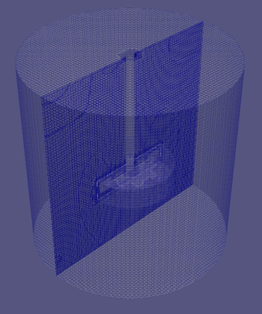
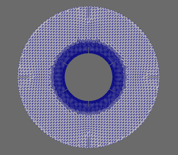
castellatedMeshControls > refinementRegions
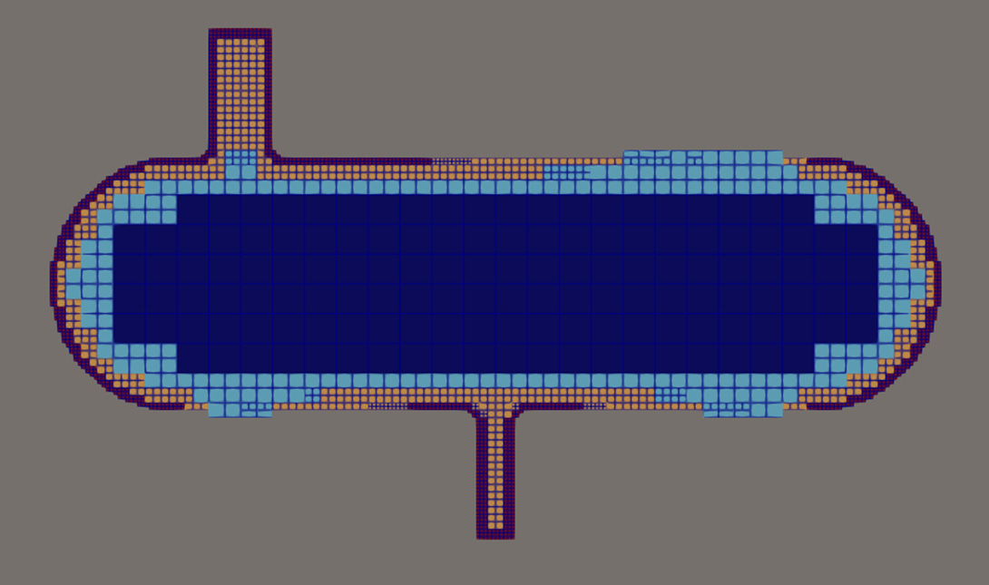
-
Controls the refinement in any selected region
-
Can use built-in shapes to constrain refinement area
-
You can see larger, inner region being marked using a “searchableBox”. No results to share as I ran out of time!
castellatedMeshControls > nCellsBetweenLevels
-
Controls transition smoothness between refinement layers
-
Affects the refinements made by other settings, default is 1:2, ideally should be set to 3 in most common cases
castellatedMeshControls > resolveFeatureAngle
-
Controls edge detection and surface resolution
-
Lower gives sharper edge results, with more edges picked up in processing
castellatedMeshControls > maxLocalCells / maxGlobalCells
-
Used by the cell refinement process, so should be kept as high as possible (based on your hardware)
-
Control when the meshing process should be terminated (safety)
The other parameters really provide a greater degree of control for the more complex of geometry capture and mesh requirements.
I’ve yet to assess snapControls and addLayersControls settings, but plan to share in future posts.
A structured, detailed guide with complete clarity is in the works!
I’ve generated countless meshes for my industrial design work for an array of complex geometry using some well-known commercial and open-source tools.
After a while you begin to notice some patterns and the individual buttons / commands ultimately end up giving you a mesh to be proud of.
snappyHexMesh has always been intriguing to me as an open-source solution as well as the fact it’s adopted by academics as well as some sections of industry (including some motorsport teams!).
I’ve come to know it can be sensitive to some settings, but most of this is controllable when you understand how it works.
But it’s easy to literally waste hours and days trying to generate and refine your mesh with it without an effort to understand how it works.
I’m in the middle of writing a structured, detailed guide on meshing for OpenFOAM using snappyHexMesh (40% done), continuing “The OpenFOAM Diet” series, I launched back in September last year.
(P.S. I’m deciding whether to keep it available for free to upgrading subscribers or offer it as a stand-alone guide…)
Thanks for reading this week!